Home automation: heating with ebus and Bulex
One of the targets of my house automation was to integrate heating. Having some familiarity with heating systems, it was already clear that interfering with the internal regulation would be a big no-no. Ideally the heating system needs to offer some kind of open interface to accept sensor values normally sent by a thermostat, but now from the house automation components instead.
The requirements:
- retrieve basic information from the system. Is it active? Are there any errors?
- replace the wall thermostat with house automation components and software
- control the temperature of every room separately (where there is need to at least)
So the journey started to boldly go where no man has gone before; asking the heating guy if he could deliver a module that offers some kind of “API” to do this. As it turned out, we fell out of warp pretty fast. I will really try to limit my rant here, but heating manufacturers live in another time-space continuum. Where most software companies need to reinvent themselves every 10 years or so, heating manufactures can do what they want so it seems. Instead of offering a somewhat flexible interface, most of them are starting to sell “Internet thermostats” to end users. Which is great if you want to retrofit but not if you want to integrate in a real house automation system. Of course, those modules can probably be ‘hacked’ in the sense that if a mobile app can operate it, it must have some kind of interface. However, most of these modules still depend on a fixed thermostat in the house for transmitting the actual room temperature. So it will only be a partial solution to the problem.
To be fair, there are vendors that offer complete integration solutions. Buderus for example offers a KNX module for this, but these are ranged for “professional customers” for integration in building control. They are expensive, require you to have an even more expensive control unit (only those units allow to connect the KNX module) and it appears that in the case of Buderus using the KNX module means that all regulation has to be done via the module as it takes over the internal regulation. The most realistic option seemed to be Viessmann together with the Vitogate 200 KNX module. This module allows high level operation replacing a thermostat while leaving all other regulation up to the heating system. The problem however was the overall price tag. A Viessmann system would be 3 times more expensive than comparable systems.
So, in the end I decided to go with Bulex. For the record, Bulex is a well known brand in Belgium. In France they are known as Saunier-duval and in Germany as AWB. These brands are the exact same and all belong to the Vaillant group and offer a good price/quality deal. They don’t have all those nifty modules or possibilities you get with brands like Viessmann, hell, don’t even expect a decent manual, but quality wise they are more than OK
![]()
Fortunately, after some investigation it turned out that not offering any integration modules does not have to be a show stopper per se. Bulex, like other Vaillant products, use Ebus as a communication medium between devices (Wikipedia). Ebus is more or less open in the sense that information on how the different layers should work is publicly available: Physical and data-Link layer and application layer. This information is enough to build software yourself that can send and receive commands. Besides the software one also needs a module that can be physically connected to the ebus. As it turned out, there is already an existing solution for both, back in business we are!
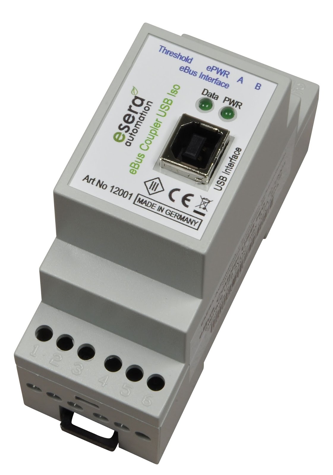
The ebus USB adapter (I got mine here: eservice-online) is something that can be custom build. However, at a price of 75euro this was not worth it for me.
Some warning statements: there is also a Ethernet version of the ebus adapter on eservice-online. As I started out with this adapter first, my experience is that this does not work as expected. The adapter seems to buffer values that it reads from the bus and sends them with a delay over the network. While this is not an immediate problem, it makes it difficult to discover which command does what as there is no instant relation between doing and action and seeing the command in the software. While this “buffer” value can be adjusted, I was not able to get it to work properly. Another problem is the configuration of the module (like ip address, …). For that it requires a piece of crappy software (that only runs on windows) and is rather problematic to work with. my advice: use the USB adapter. It costs 50% less and the device itself requires no configuration. In my case plugging it in on a raspberry PI 3 was all that needed to be done.
![]()
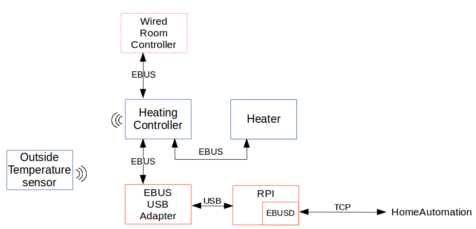
Next, besides having an adapter, one also needs software. Over at Github there is a project called ‘Ebusd’, John30, the creator, is doing an awesome job building and maintaining this which does everything you want with ebus (https://github.com/john30/ebusd/). Without his effort my little project would probably never existed. The software comes with MQTT support and a TCP server so communicating with it is a breeze. So basically you hook up the adapter to a spare ebus connection on the control unit, plug-in the adapter via USB into a device (RPI in my case), launch ebusd et voilà, you are seeing all commands that are being send on the bus. The eventual schema looks like this:
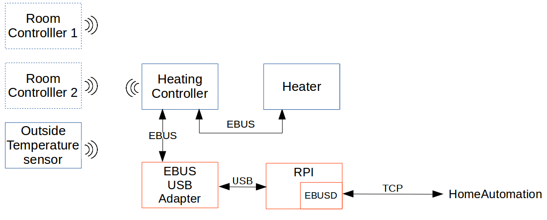
Some background: the “Room controllers” are parts of the original Bulex system (in my case bulex exacontrol wireless). They are the wireless thermostats that we are trying to replace. They communicate with the heating controller (in my case Bulex examaster) using some wireless protocol which is not important anyway as our target is to eliminate them. The outside temperature sensor is important as this is a weather depended regulation. As an extra we will also be reading out it’s value so we can show he outside temperature without having to buy a standalone temperature unit.
Now, the tricky part are the commands. While ebus might be a standard, the commands used by heating vendors are not. Ebusd comes with config files for some devices that have already been discovered. Based on the device id (broadcasted on the bus) ebusd will load a matching config file and display the representation of the commands.
Unfortunately for Bulex there is no corresponding mapping to be found. But, playing around with other Vaillant mappings, the first command I found was the one for the outside temperature: 15b50903293c00 The address layout can be seen here: https://github.com/john30/ebusd/wiki/HowTos quote:
“QQZZPBSBNNDD / NNDD = count Here, QQ is the source address, ZZ is the destination address, PBSB is the primary and secondary command byte, NN is the number of data bytes DD following, and count is the number of times, the message was seen on the bus.”
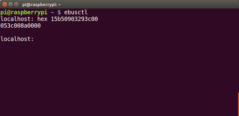 When sending this command using ebusctl (a CLI for ebusd, which you get after installing ebusd) the response is: 053c008a0000. Based on a response without pre existing mapping one cannot know which byte is what However, since the outside temperature is fairly standard, I found out in the existing mapping files that the the two bytes 0x8a00 represent the temperature value in data2c datatype.
 Given the ebus standard we can convert this to decimal as follow: reverse byte order 0x8a00 becomes 0x008a. Convert high byte to decimal and multiple by 16. 0x00 = 0 and 0 * 16 = 0. Convert high nibble of low byte to decimal (0x8 = 8 decimal) and add it to result: 0 + 8 = 8. Convert low nibble of low byte to decimal (0xa = 10) and divide it by 16 (4/16= 0.625) add it to the result: 8 + 0.625 = 8.625°C
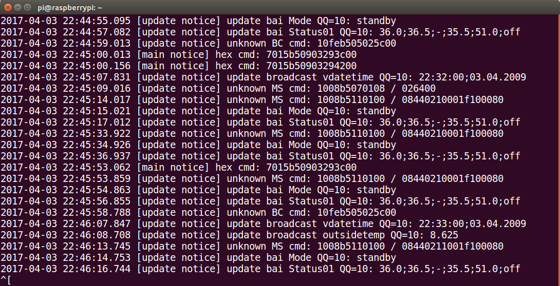
This can also be verified by looking at the ebusd log file. Since I started ebusd with a vaillant config file, it will try to decode every command it sees. The outside temperature is one of the commands that are apparently a bit universal over the vaillant products and is one of the few which is recognized ootb. The temperature is also broadcasted by the control unit on a regular base (you can actively query for it using the command above, or wait for it to pass by on the bus via the broadcast). So here we see ebusd decoding the value of the temperature broadcast. As can be seen, this matches.
So what we have now is an interface into the heating system. As ebusd runs a TCP server ootb, we can now simply write some code to send the commands and receive the value:
public List<string> send(EbusCommand ebusCommand) throws Exception {
  try (Socket clientSocket = new Socket(getInstance().getEbusdIp(), getInstance().getEbusdPort())) {
   List<string> results = new ArrayList<>();
   DataOutputStream out = new DataOutputStream(clientSocket.getOutputStream());
   BufferedReader in = new BufferedReader(new InputStreamReader(clientSocket.getInputStream()));

   for (String command : ebusCommand.getEbusCommands()) {
    logger.debug("Writing to ebus: hex " + command);
    out.writeBytes("hex " + command + "\n");
    String result = in.readLine();
    logger.debug("  Result:" + result);
    if (!ebusCommand.withResult() && !result.equals("00")) {
     logger.error("Command hex " + command + " resulted in " + result + " should  have been 00");
    }
    results.add(result);
    in.readLine();
    sleep(200);
   }
   return results;
  }
 }
The code above can be found here (https://github.com/koen-serneels/HomeAutomation) but the bottom line is it sends “hex “ + command, in the above example “hex 15b50903293c00” and it receives “15b50903293c00”. The only thing left to do is extract the payload and convert the datatype.
So far so good!
Unfortunately this is where the warm cosy feeling went cold and dark. The assumption was that when changing the temperature on the wireless thermostat the corresponding command would be visible on the bus. After capturing it it should have been possible to simply replay the commands using ebusd, creating an index of useful commands. Unfortunately this was not working. The most likely explanation was that the wireless thermostat would communicate directly with the control unit but the control unit would be smart enough to not put these command on the wired bus as it is the final receiver.
After giving it some thought I decided to place a small bet and get myself a wired ebus thermostat instead (the normal bulex exacontrol). Making the schema like this:
Luckily this worked. Commands issued by the wired thermostat became visible on the bus. In hindsight, getting a wired thermostat was not really required. What happens is that when the control unit receives a command (no matter the source, wireless or wired) it changes an internal register based on the received the command. So the command basically addresses a register with a given value. Scanning all of the registers before changing the temperature and scanning them again after the change, would also reveal the changed registers without having to intercept the actual command.
This is a bit more hassle as reading all the registers takes some time (~2 minutes) and one also need to filter out the changes done by the system in the mean time (these changes would be triggered by internal housekeeping, time depended stuff, updates from other ebus connected devices such as the heater, …). To be sure one has the real register related to the command the procedure needs to be repeated a couple of times, diffing the files each time and eliminating the non related ones. Anyway, this technique works and it is also required to find out registers for internal state which are never read or send to/from thermostats in the first place and works no matter the type of thermostat.
Below a snippet (https://github.com/koen-serneels/HomeAutomation) from a small tool that scans the range for 0x29 from 0x00 till 0xFF
public class EbusRegisterReader {
 public static void main(String[] args) throws Exception {
  String template = "15b5090329%s00";

  try (Socket clientSocket = new Socket("192.168.0.10", 8888)) {
   List<String> results = new ArrayList<>();
   DataOutputStream out = new DataOutputStream(clientSocket.getOutputStream());
   BufferedReader in = new BufferedReader(new InputStreamReader(clientSocket.getInputStream()));

   for (int i = 0; i < 255; i++) {
    String cmd = String.format(template, leftPad(new BigInteger("" + i).toString(16), 2, "0"));
    out.writeBytes("hex " + cmd + "\n");
    String result = in.readLine();
    System.err.println(cmd + " - " + result);
    in.readLine();
   }
   out.close();
   in.close();
  }
 }
}
There seem to be two ranges: 0x29 (as shown in the example) and 0x0D. Both ranges can be read. The bytes following denote the rest of the register. I’m not really sure what the 0x29/0x0D is, it’s either an instruction for reading or simply a part of the register. Anyway, scanning both 0x29 and 0x0D from 0x0000 till 0xFFFF should scan most if not all available registers. Note that scanning all of these addresses takes a lof of time, especially since only a small portion of the address can actually be read (the others produce a read error). To fix this one can simply write the addresses that returned something meaningful to a file and use that file the next time instead of re-scanning everything.
Another important aspect is that the control unit identifies the heating circuit (HC) that needs to be controlled using the base or source address. In my case there a two heating circuits. One for the floor heating at ground floor and one for the floor heating at the first floor. When thermostats are first linked with the control unit, each gets a specific base address which is then later on used to identify the HC to be operated. So, in my case, sending a command with source 0x30 operates HC1, sending that same command with source 0x70 operates HC2. The command in combination with the source address determines which HC will be operated. These source addresses seem to be fixed, at least for my configuration (if there are more heating circuits or other components these address could be different). Thankfully ebusd implemented my change request to support changing source address on the fly (https://github.com/john30/ebusd/issues/50) so now it is possible to send along the source address with the command as opposed to the source address only being statically configurable at ebusd startup.
Note that depending on the HC, registers have sometimes different meaning. So a register that accepts the desired temperature (for example) could be different for HC1 and HC2. To be sure you have to test with both circuits to verify the actual registers to use. In my case this makes sense as HC1 and HC2 are of a different type. I won’t go into detail here, but by default the system only allows 1 low temperature circuit or ‘mixed circuit’ (for floor heating) and 2 where needed, so we came with a workaround by using a 2nd HC but of type ‘high temperature’, but configure it to not exceed 38°C water temperature making it virtually equal to a low or mixed circuit. While the control unit operates the mixing valve for HC1 (as being a genuine low temperature/mixed circuit) it does not for HC1. This is however not a problem as the heater modulates, so it does not need the mixing valve in the first place. It would be needed if there was an actual high temperature circuit (for traditional radiators for ex.) but this is not the case, so all good!
At this point we have created an interface into the heating system. With some more playing with said techniques, following commands were found:
- Get the outside temperature
- Get heating demand status of heating circuits 1 and 2
- Get the target water temperature
- Get heating circuit enabled status
- Set the desired temperature
- Set the current temperature
- Set heating circuit enabled
All the commands are available here: https://github.com/koen-serneels/HomeAutomation/tree/master/src/main/java/be/error/rpi/ebus/commands
 Finally we need something for independent room temperature control. Whether or not this makes sense depends on the situation and type of house. In my case, the ground floor is a more or less open space, there it would not make sense to control individual floor heating circuits. However, on the first floor there are different bedrooms and a bathroom each having different temperature requirements.
In case you're not familiar with floor heating, it are basically different circuits of tubes connected to a manifold. Normally there is at least one circuit per room (possibly more if the surface requires it). So if a room has lets say 2 circuits, one could control the temperature by opening or closing valves on the manifold. This is exactly what we are going to do. Each valve on the manifold is operated by an electronic valve. In my case it are 230v NC valves (in german: stellantrieb) for example https://www.theben.de/en/Products/Accessories/Climate/Actuator-ALPHA-5-230-V
Finally we need something for independent room temperature control. Whether or not this makes sense depends on the situation and type of house. In my case, the ground floor is a more or less open space, there it would not make sense to control individual floor heating circuits. However, on the first floor there are different bedrooms and a bathroom each having different temperature requirements.
In case you're not familiar with floor heating, it are basically different circuits of tubes connected to a manifold. Normally there is at least one circuit per room (possibly more if the surface requires it). So if a room has lets say 2 circuits, one could control the temperature by opening or closing valves on the manifold. This is exactly what we are going to do. Each valve on the manifold is operated by an electronic valve. In my case it are 230v NC valves (in german: stellantrieb) for example https://www.theben.de/en/Products/Accessories/Climate/Actuator-ALPHA-5-230-V 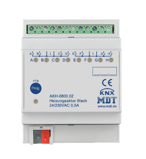 The valves are controlled by an MDT KNX heating actuator (http://www.mdt.de/EN_Heating_Actuators.html). The actuator can function in different modes. In automatic mode you pass it the current room temperature and based on the set-point temperature it will in PWM style drive the valve so that it obtains the required temperature. There is also manual mode in which it simply opens or closes the valve. The manual mode it's just acting as an relay, turning the valves on or off. In my setup the actuator is in manual mode. The actual controller is self-written. In this case I could just have used 'simple' relays instead of an actuator, but relays also need to be controlled, space and energy efficient, you need to know which 'position' they are in, durable and so forth. In the end the KNX controller is not that much more expensive and it can still do some important housekeeping stuff that I do not need to program, for example it can operate the valves from time to time in summer mode to make sure they don't get stuck. Ok, thanks to these valves it is now possible to control each room independently. Each room corresponds to at least one valve, some rooms have multiple circuits, in that case the combined vavles for that room will be operated as one.
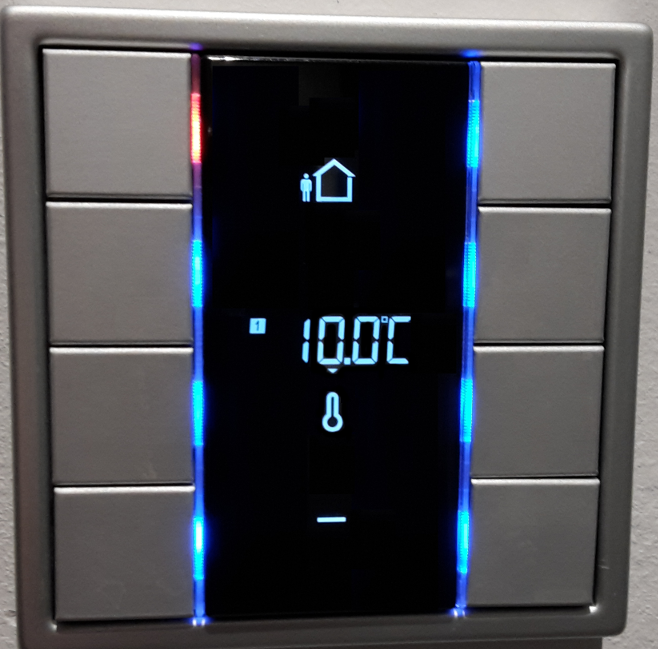 The only thing we need to do now is glue everything together. For this I have written a heating controller that gathers the current/required temperatures, communicates them to the control unit via ebus and operates the valves.
The current and required temperatures are obtained from sensor in each room. In my case these are build-in into the KNX wall switches. Even though most rooms have motion sensors, where it makes sense, there is also a switch in every room allowing an elegant way (among others) to do these measurement. Next to setting the desired temperature via the web app, it can also be done on the switches directly. So what basically happens is that the room temperature collector receives the current and desired temperature (from the wall switches and/or web app) and sends them to the heating controller. Based on this it knows if there is heating demand (=there is at least one room of which the desired temp is greater than the current temp) and which room has the highest heating demand. This software is running on the same RPI as ebusd is running.
The only thing we need to do now is glue everything together. For this I have written a heating controller that gathers the current/required temperatures, communicates them to the control unit via ebus and operates the valves.
The current and required temperatures are obtained from sensor in each room. In my case these are build-in into the KNX wall switches. Even though most rooms have motion sensors, where it makes sense, there is also a switch in every room allowing an elegant way (among others) to do these measurement. Next to setting the desired temperature via the web app, it can also be done on the switches directly. So what basically happens is that the room temperature collector receives the current and desired temperature (from the wall switches and/or web app) and sends them to the heating controller. Based on this it knows if there is heating demand (=there is at least one room of which the desired temp is greater than the current temp) and which room has the highest heating demand. This software is running on the same RPI as ebusd is running.
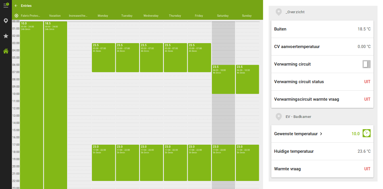
Finally some screenshots how the control looks from the webapp (the webapp is currently created via Loxone). On the right, the general status and the temperature control from the bathroom is shown. Currently it's summer and the heating is turned off. In that case all rooms go to"frost protect" mode meaning they are set to 10°C. On the left there is the schedule that is activated from the moment the heating goes out of frost protection