Downlights With KNX And Dimming
For downlights I found good value for money in the Abinshte (by Dmlights) constant current LED armatures. They were (back in 2016) only like ~50euro/piece for 1000+ lm and 15watts (50 degrees reflector, 700mA). The armatures are also very sturdy with a gigantic heat sink, but above all I really liked the design.
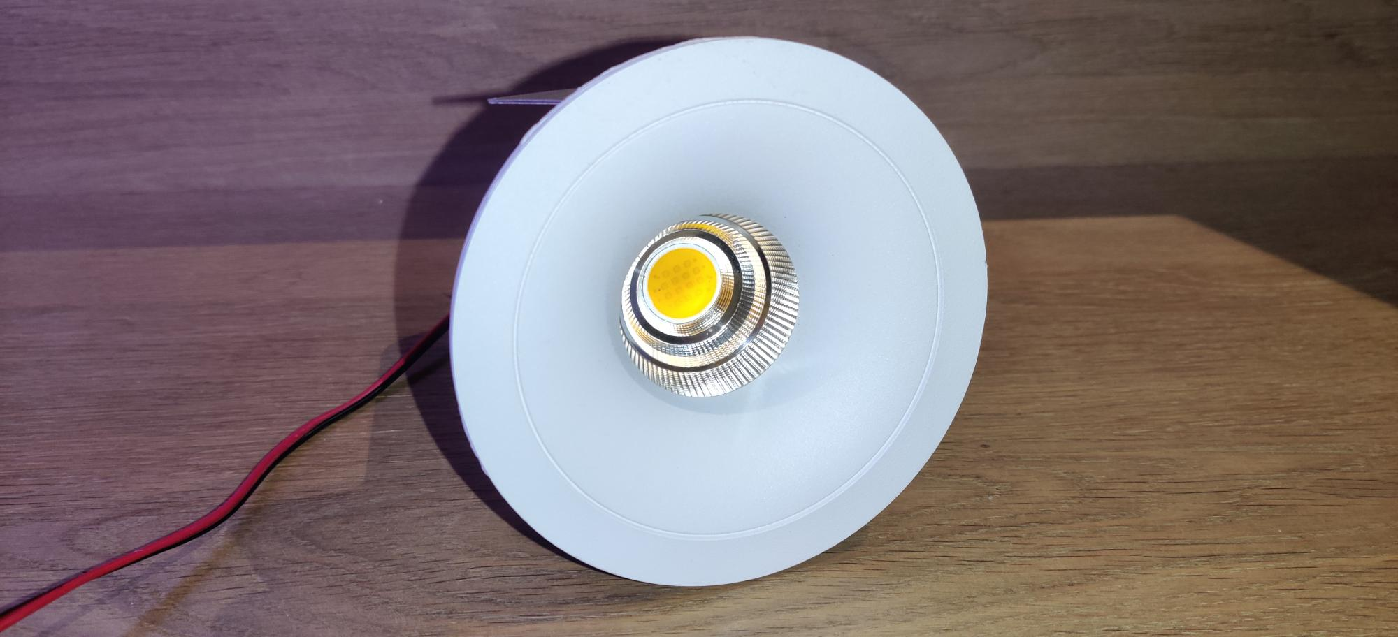 Downlight view from bottom
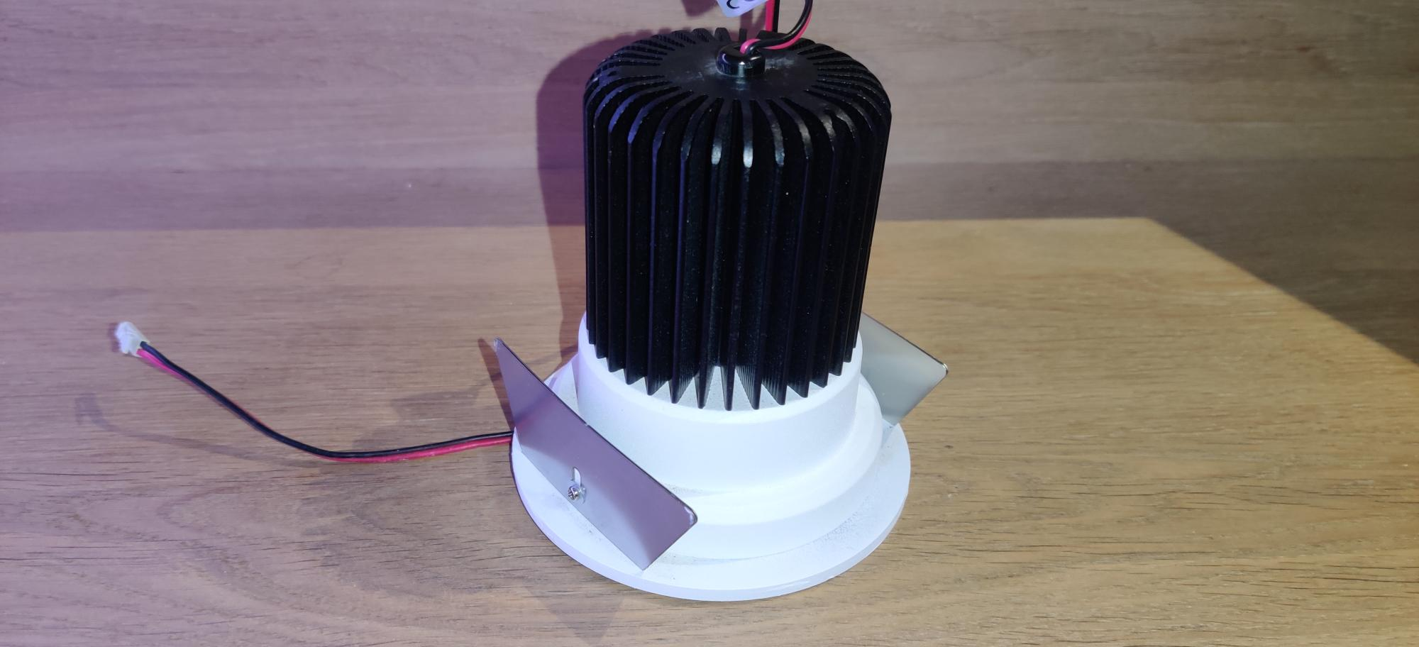 Downlight upright view
By default the units were foreseen with springs for plasterboard/hollow ceiling mounts but the springs can easily be replaced with metal plates for concrete ceiling mounting. If they are mounted in concrete, 100mm holes are needed, and depending how much height there is in the ceiling, the holes will probably need to be drilled completely through as the unit is about 15cm in height
 plasterboard/hollow ceiling mounts
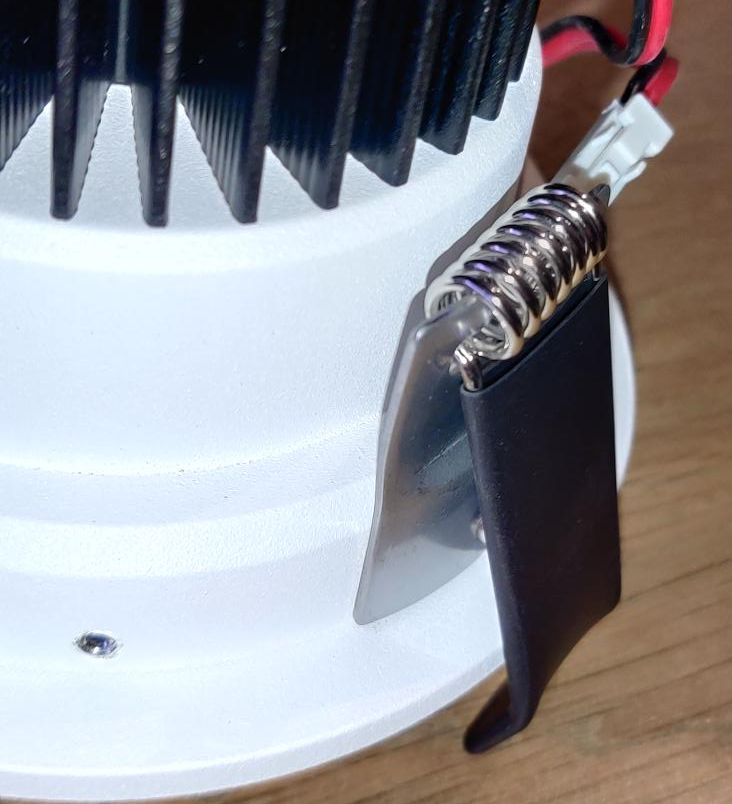
 switched with metal plates for concrete mount
Now, one of the important aspects of downlights is being able to dim them, so it is important to chose the components well. There are KNX options but they are either constant voltage (for driving led strips for example) or phase-cut dimmers for specific loads such as halogen or other variants supporting fluorescence lights.
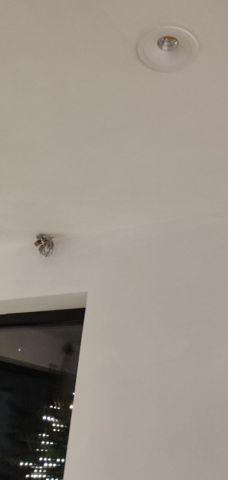 Downlight installed into the ceiling
Because of this the driver that I decided to use was the Meanwell LCM series. They are good value for money and come with different interface options. There is the 0-10v/pwm/resistance version for dimming, a DALI version and these days (didn’t exist back then) even a KNX version with integrated bus coupler. The best option would be opting for DALI but to keep expenses down I opted for the 0-10v version combined with a custom DAC solution involving a raspberry, to much self written software, and i2c.
Note: there is also a neat 1-10v KNX dimmer from MDT ( https://www.mdt.de/en/products/product-detail/actuators/dimming-actuators/dimming-control-device-akd.html) which does exactly this in a single component. However, tests pointed out that the minimum dim level was still to high compared with a standard DAC solution. The difference is not that big, but as the downlights are 15watt, it was noticeable enough to opt out for this solution.
Building stuff is great, but as we all know, there comes a time things need to go ¨into production¨ and then 8 years later you start to explain to @KristofJanssens how the setup works and then realize that you have no idea anymore how it works. So! Time for some documentation and share it in the mean time :)
High-level design:
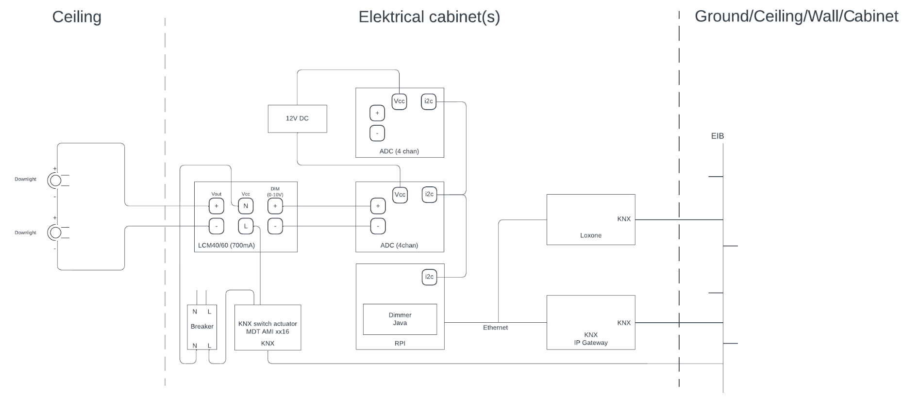
Taking the design, right from the already discussed downlights, are the LCM units. Where the downlights are physically wired per two a LCM40 (40watt) is used, where they are physically wired per 4 a LCM60 (60watt) is used. For example there might be a room with 6 downlights, but if they are controlled per 2 (each pair connected to an LCM40) they can later be logically controlled per 2. But other rooms might have 4 downlights controlled as one with an LCM60, in that case there is no other option than to control them by 4. This decision was made depending on the room to get maximum control in the places where it might come in handy when for example using scenes. It would be cool if they could all be controlled per 1, but that was a trade-off to keep the number of drivers down.
The LCM´s are mounted vertically in the cabinet. It has two metal clips with a hole that allows for vertical mounting. These are screwed onto a plastic DIN rail clip to fix them om the rail. For this I had to install two rails. It is a clean solution but takes up some space. The LCM connections consists of: 230v AC, DC output for the downlight circuit (as they are constant current they are connected in series), dip switches for the output current (configured to 700mA in this case) and the 0-10v DIM input.
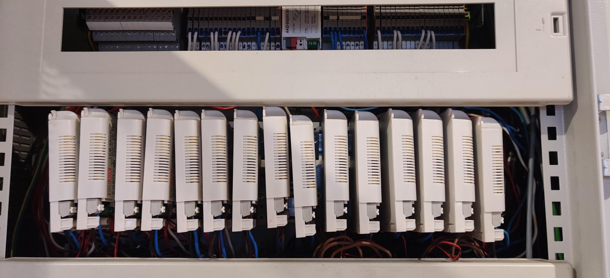 View of one of the cabinets with LCM´s mounted
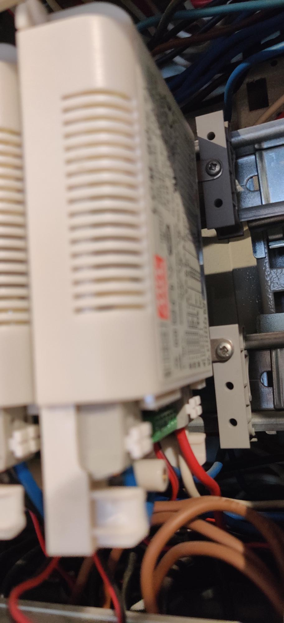 Plastic DIN clips for vertical mounting
The DIM input can be used with three different signals. The input is auto-sensing so supplying a signal out of these three options suffices, in my setup a 0-10v signal is offered.
Dimming via 0-10v
Dimming via PWN (100Hz – 3KHz)
Dimming via variable resistance
The LCM also has a SYN connection for syncing with other LCM modules (primary/secondaries). However, in my case I need to be able to control each LCM driver individually so I don´t use it. But even for a group of for example 4 downlights , controlled per 2 via 2 LCM´s each connect to an individual DAC channel, they still dim perfectly together in case you want to logically control them via software as one (at least nothing that can be seen with the naked eye). So even if you decide that 2 LCM´s need to be operated as one, I don´t fully understand what the SYN function brings (at least in case of 0-10v), as you can simply wire the 0-10v from the first unit to the second unit instead. It might probably easier to use the Meanwell syn-cable instead (instead of getting 2 wires in a single connection socket). For the KNX (and perhaps DALI) version it probably makes more sense in that case since the secondaries do not take up a bus connection, and it´s perhaps possible to combine the KNX version with the non-KNX version (as it is cheaper)
The next component, to right of the LCM on the design, is the i2c DAC. I got the kit from here https://www.horter-shop.de/en/home/93-kit-i2c-analog-output-module-4-channel-10-bit-4260404260752.html. This needs some soldering love, but it only consist of basic components and the IC´s have DIL sockets so you can solder the sockets on without risk damaging the IC (the IC is plugged-in after the socket is soldered on). My soldering skills are near to zero, so that fact that I got it done is an indication how easy this is. Do opt for the plug-in terminals as they allow to separate the top-end (where the wire is connected) from its base. This allows to easily replace a unit without needing to unscrew all the wires. To mount the DAC I used the DIN mounting frame https://www.horter-shop.de/en/i2c-din-rail-modules/106-mounting-frame-for-din-rail-4260404260691.html.
Note: the unit on the right is an alternative (https://www.lucid-control.com/product/lucidcontrol-ao4-4-channel-analog-output-usb-module/) that comes pre-assembled and works via USB instead of i2c. I´m using this module as well as it was a test, but it serves the exact same purpose and it (expect on the software part) interchangeable with the i2c DAC PIC.
The DAC is connected to the RPI (shown below the DAC on the design) via I2C. Before the DAC module can be used with the RPI it needs a TTL-level converter https://www.horter-shop.de/en/i2c-din-rail-modules/174-304-i2c-repeater-for-raspberry-pi-finished-4260404261162.html#/26-terminals-plug_in_terminals I opted for the pre-build version, as for a couple of euro´s extra I did not want to risk to solder it myself (this unit, unlike the DAC, contains smaller components and the IC´s are directly soldered without DIL sockets). The unit can be plugged-on as a hat sitting on top of the RPI GPIO. Only one such module is needed as it basically does nothing more than voltage level conversion for the i2c bus
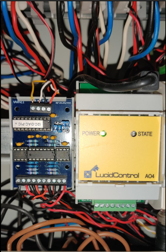 i2c DAC board (left), lucid control AO4 usb (right)
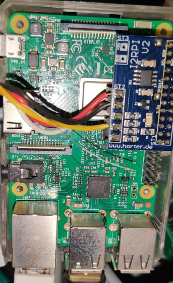 Raspberry with i2c hat
Below is a more in detail wiring diagram illustrating the connections for the RPI, DAC and DIM input for the LCM module:
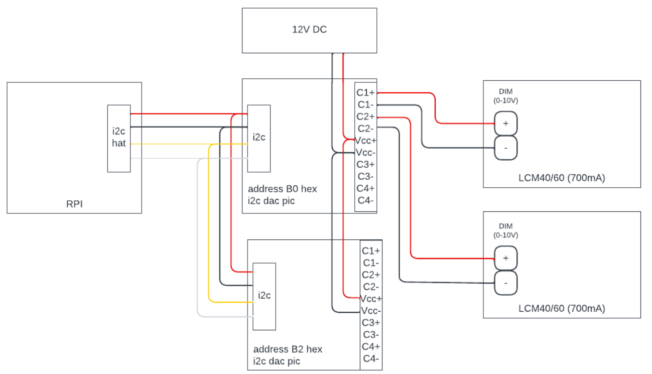
The last component that needs some explanation before we can go to the software side is the KNX switch actuator (located below the LCM on the high level design) for turning the driver (and in extend the LED) on and off. Operating a downlight requires two steps: turning on the actuar channel for the driver and steer the DAC output to put the downlight in the desired light intensity.
The KNX group addresses for the kitchen are in middle group 5/0 and are as follows (group address/function object/description):
| 5/0/0 | Actuate downlights pair 1 | Bound to the switching actuator (MDT AMI) object ¨channel switch on/off¨ and object ¨state¨ |
| 5/0/1 | Actuate downlights pair 2 | Bound to the switching actuator (MDT AMI) object ¨channel switch on/off¨ and object ¨state¨ |
| 5/0/2 | Actuate downlights pair 3 | Bound to the switching actuator (MDT AMI) object ¨channel switch on/off¨ and object ¨state¨ |
| 5/0/3 | Taster status led | Bound to the taster status led, object for switching led on/off and object for color selection (red) |
| 5/0/4 | Taster dim | Outputs the selected dim value. Configured as long press = dim up or down |
| 5/0/5 | Taster switch | Outputs if the taster is operated. Short press toggle on/off |
| 5/0/6 | Button switch (update) | Updates the button state |
| 5/0/7 | Actuate combined | Bound to the three switching actuator (MDT AMI) object ¨channel switch on/off¨ and object ¨state¨ to allow turning all pairs on/off together |
Then there are ¨virtual¨ group addresses, in the sense that they are not connected to a real knx sensor or actor, but used by loxone and self written software. For loxone absolute dim control this is middle group 14/0 and for the Loxone dim feedback this is middle group 15/0:
| 14/0/1 | Kitchen absolute dim value |
| 15/0/1 | Kitchen absolute dim value feedback |
The loxone setup:
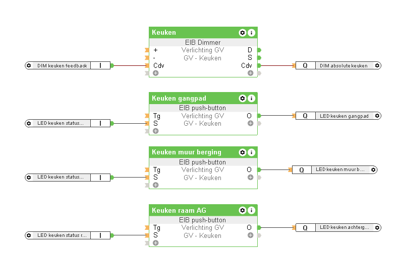
The first component is a ¨EIB dimmer¨ which is a specific component that loxone offers to integrate with knx components. The ¨Cdv¨ input is connected to a Loxone EIB sensor component listening on GA 15/0/1. The Cdv input is a sensor input that listens for the actual dim value. It only updates the visualization and does not control any output. The Cdv output is the opposite and is connected to a Loxone EIB actuator component sending to GA 14/0/1. Telegrams are transmitted to this GA from the moment the dim value is changed via the loxone visualization.
The other 3 components are Loxone EIB push buttons (configured as on/off switch). They allow to control the 3 pairs of downlights available in the kitchen. For example, if the dimmer is operated from the loxone visualization, the Java module (discussed next) listening on GA 14/0/1 will by default turn on the 3 pairs of downlights. If that is not desired it is possible to turn of each pair of downlight via the EIB push button. This is off course a manual operation (and thus not a real scene function) and is only foreseen for those cases where there is a reason to switch of pairs.
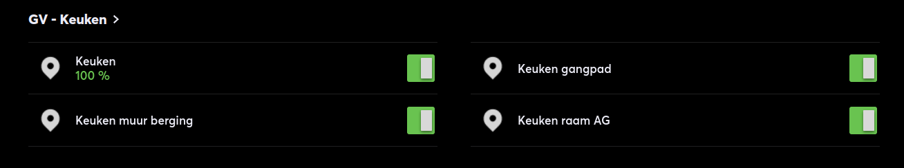 Loxone visualization - dimmer and switch control for individual downlight groups
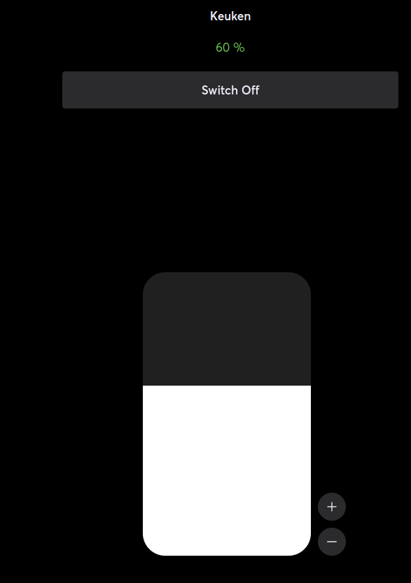 Loxone visualization - dimmer control allowing turn on/off and 0-100% value
What fails is the central logic that connects these interfaces. This module is written in Java and runs on the RPI. This module could run everywhere, but as it needs access to the i2c bus (and usb for the lucid control component) it just makes sense to directly run it from the rpi.
There are 3 core libraries used: calimero allows to use knx from Java (over IP), pi4j allows to use low level functions integrated on the rpi, such as: GPIO, I2C, SPI, PWM and Serial, here it is used for the i2c communication. Then lucidio which is the library offered by lucid control to operate their devices via usb.
This is all combined in the dimmer logic. The dimmer is then configured with all the relevant GA´s. There is a lot of code behind it to be able to send and listen for telegrams using calimero, to actually control the DAC and then of course the dim logic with soft on/off support. Below is the most relevant part to illustrate the glue between the different components (DimmerKeuken.java):
public class DimmerKeuken implements DimmerConfig {

@Override
public Dimmer start() throws Exception {
   return new DimmerBuilder() {
       {
          	name(KEUKEN);
           	boardAddress(0x5B);
           	boardChannel(2);
           	delayBeforeIncreasingDimValue(15);

           	outputGroupAddressesForActorSwitchingOnAndOff("1/0/6", "1/0/7");
           	outputGroupAddressesForVisualisationStatusFeedback("15/0/1");
           	outputGroupAddressesForSwitchLedControl("1/0/3");
           	outputGroupAddressesSwitchUpdate("1/0/5");
           	inputGroupAddressForOnAndOff("1/0/5");
           	inputGroupAddressForDimStartAndStop("1/0/4");
           	inputGroupAddressForAbsoluteDimValue("14/0/1");
       	}
     }.build();
   }
}
- Board address and channel is required for the i2c communication to identify the desired adc board.
- inputGroupAddressForOnAndOff listens for telegrams that are emitted when the push button is operated on the taster. The taster will emit a telegram that is then received by our dimmer logic. The dimmer logic will then send a telegram to the GA configured with outputGroupAddressesForActorSwitchingOnAndOff which controls the three actuator channels
- inputGroupAddressForDimStartAndStop is to receive the dim trigger. The dimming can be configured in different modes on the taster, but here it works via start and stop telegrams (1bit boolean). The taster will automatically send a '1' telegram when the user pushes (and keeps pushing) the button longer than x msec as the button goes to dimming mode and a '1' will be send to this GA, meaning 'start dimming'. When the user releases the button, the taster will automatically send a 'on release' telegram being '0' which the software will interprete as ¨stop the dimming at the current value¨. This means that the dimming percentage ¨state¨ is retained within the software and not within the taster (the taster only retains on/off state)
- inputGroupAddressForAbsoluteDimValue is our input we get from loxone. In case the user operates our dimmer via the loxone visualization, it receives an absolute dim value. In this case the dim value is retained in both the software and loxone.
- outputGroupAddressesForVisualisationStatusFeedback is used to update the loxone visualization in case the dimming is operated via the taster. The software will (depending how long the push button was pressed) calculate the absolute dim value which is then send as feedback to loxone to update the visualization
- outputGroupAddressesSwitchUpdate and outputGroupAddressesForSwitchLedControl are used to update the switch state of the button when operated from the visualization, the taster needs to know if the light is on or off, to avoid a ¨double press¨ as the on/off state (in contrast with the dim value) is retained within the taster. For example, if the light is turned on via loxone, and the taster receives no update from this, it still thinks the light is off. If then the light is turned off via the taster, it will on first press first emit a ¨on¨ telegram requiring a second press to turn the light off. The outputGroupAddressesForSwitchLedControl is to control the LED of the taster
Some noteworthy classes:
- Convert a 0-100% to 0-1023, making sure it is always 2 bytes as required by the DAC (source)
- The class responsible for writing the dim value to the DAC using i2c (source)
- Check if the DAC is i2c or lucid control, the lucid control only requires a single line lucidControlAO4.setIo(channel, new ValueVOS2(convertPercentageTo10Volt(targetValue))); (source)
- KnxDimmerProcessListener uses calimero to listen for the different configured GA´s and send commands to the dimmer logic (source)
When already having control over the knx bus from our software module in Java, we have a choice of configuring scenes directly from the software, as the functions (for knx devices having scene support) that can be controlled via the scene can always be controlled externally via separate function objects as well. As I prefer a more centralized approach for a scene (in the sense that you can immediate see all the devices involved and their values) I opted for the latter. For example in this class (Gv.java)
private void sceneOne(boolean on, ProcessEvent e) throws Exception {
    if (on) {
    	getInstance().getKnxConnectionFactory().runWithProcessCommunicator(pc -> pc.write(new GroupAddress("11/0/1"), true));
	} else {
    	getInstance().getKnxConnectionFactory().runWithProcessCommunicator(pc -> pc.write(new GroupAddress("11/0/1"), false));
	}

	eethoek.interrupt();
	zithoek.interrupt();
	keuken.interrupt();
	keuken.putCommand(new DimmerCommand(new BigDecimal(on ? 1 : 0), e.getSourceAddr(), on ? active(new GroupAddress("5/0/2")) : inactive()));
	zithoek.putCommand(new DimmerCommand(new BigDecimal(on ? 1 : 0), e.getSourceAddr(), on ? active(new GroupAddress("5/3/1")) : inactive()));
	eethoek.putCommand(new DimmerCommand(new BigDecimal(on ? 1 : 0), e.getSourceAddr(), on ? active(new GroupAddress("5/1/0")) : inactive()));
}
we listen to the 11/0 range that is dedicated for scenes. If a telegram is received 3 pairs of downlights are turned on (the others in their group are turned off implicitly via the reset) on their minimum dim value. The scene remains active until turned of. For example, one of the downlight pairs involved is in the kitchen. If at some point more light is needed the push button for the kitchen can be operated which will turn on the other downlight pairs. After pushing the button again the group will go to the active scene, keeping the desired pair on while turning the others off.
There is a more complex example here (Gang.java) that operates a pair of extra downlights when comming in through the front door. These lights are only operated via the scene and has some pre-conditions as they are not turned on if someone is home already.